http://www.learningaboutelectronics.com/Articles/Ramp-generator-circuit-with-transistors.php
OJO: El transistor pnp de la parte de switch estaba al revés y se giro para que el circuito funcionará, es decir la página original de arriba, tenía un error. Acá ya lo corregí.
How to Build a Ramp Generator with Transistors
In this project, we will show how to build a ramp generator circuit using transistors and a few other simple
components, resistors and a capacitor.
This circuit requires no integrated chips.
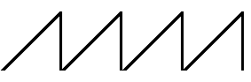
A ramp generator is a signal generator which generates a ramp waveform. This waveform increases steadly
as the capacitor is being charged until it hits its peak and then decreases even more dramatically as the capacitor is
discharged.
Being that this waveform repeats over and over again, this generator can be seen as an oscillator.
If you connect to an output device such as an LED, it will turn the LED first with low brightness and as
the amplitude of the ramp increases, the LED will get brighter. As the ramp hits its peak and starts to descend in
amplitude, the LED fades out until it turns off. The process then repeats itself over and over again.
The details of how to build this circuit and how exactly it works is described in detail below.
If you have an oscilloscope, you can check the output waveform that the circuit produces. If you do not have
an oscilloscope, then you can simply connect to an output device such as an LED to see the fade in, fade out process.
Components Needed
- 2 2N3906 PNP Transistors
- 2N3904 NPN Transistor
- 4 10KΩ Resistors
- 1KΩ Resistor
- 10nF ceramic capacitor
So in this circuit we use 2 PNP transistors and 1 NPN transistor.
Although we've designated to use the 2N3906 as the PNP
transistor and the 2N3904 as the NPN transistor, you really could use
any
other type of PNP and NPN transistor that you have. It doesn't have to
be these.
The datasheet for the 2N3906 PNP transistor is found here:
2N3906 PNP Transistor Datasheet.
The datasheet for the 2N3904 NPNP transistor is found here:
2N3904 NPN Transistor Datasheet.
Even though the transistors operate different, from a back
view of the transistor, right side up (with the terminal legs of the
transistor pointing downward),
from left to right, the terminals of the transistor are EBC: Emitter,
Base, and Collector.
So when connecting the transistors, this information is needed.
Ramp Generator Circuit Built with Transistors
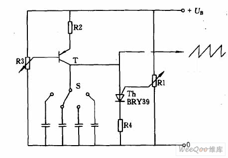
The ramp generator circuit we will build with transistors and a capacitor and resistors is shown below.
Nota: Ojo que el transistor pnp de la segunda etapa ya se arreglo para que funcionará bien.

Nota: Ojo que el transistor pnp de la segunda etapa ya se arreglo para que funcionará bien.
Below is the breadboard version of the above circuit so that you can see the
exact wiring of the circuit on a breadboard.
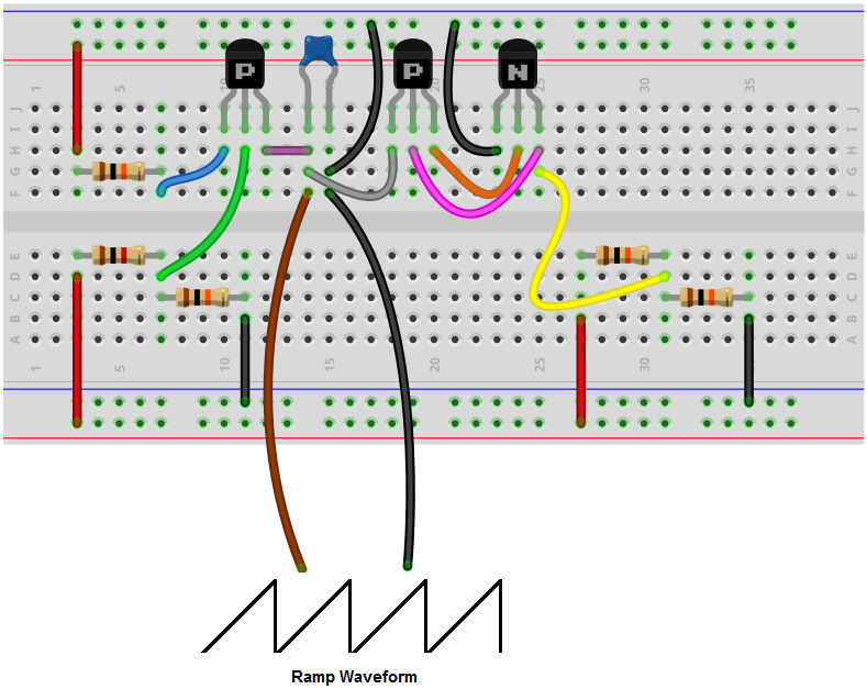
For this circuit, we are using 9VDC.
All the way to the left of the circuit, are a 1KΩ resistor and a 10KΩ resistor in parallel. These
resistors in parallel set up a bias voltage for the PNP transistor. This allows for the PNP transistor to turn up and allows
current flow from the emitter to the collector of the PNP transistor. The current flowing through this transistor is about
30 microamperes. This is the same current that gets dumped into the 10nF ceramic capacitor, charging it up. This forms
the rising edge of the ramp waveform. As the capacitor charges up more and more and the charge gets larger and larger, the
ramp on the waveform steadily rises.
Once the voltage rises to a level high enough on the
capacitor that turns on the PNP transistor that it is
connected to the anode the ceramic capacitor, then the capacitor begins
discharging. Think of it this way. When there is no power
to the circuit, no current can flow because there is no power. Once we
turn on the power, the first PNP transistor (to the
leftmost part of the circuit) acts as a current source for the
capacitor. The capacitor gets charged up by the PNP
current source. As it gets charged, the voltage across the capacitor
increases. Know that the voltage across a capacitor
is proportional to the amount of current that charges it up. As the
current flows into the capacitor, its voltage increases.
Once the voltage reaches a certain threshold, the peak of the ramp
waveform, it is high enough to turn on the second
PNP transistor. Once it turns on the PNP transistor, this PNP transistor
turns on the NPN transistor. Both transistors
are now operating in saturation mode and are fully conducting. Being
that the voltage at the capacitor is now high enough
to turn on the transistor, the transistor goes from cutoff (not
conducting) to saturation (fully conducting). Now that
current can flow through the transistor, the capacitor discharges its
current through the transistor. Once all the charge
from the capacitor has been discharged from the capacitor, then there is
not enough voltage to turn on the PNP transistor.
Therefore, the 2 rightmost transistors no longer conduct current. The
process starts over with the leftmost transistor,
the current source, charging up the capacitor again.
This creates the constant ramp waveform of charging and discharging of the capacitor.
The 2 10KΩ resistors in parallel form a voltage
divider. Since the voltage supply is 9V, it divides the voltage
in half at the midpoint between the 2 resistors, creating 4.5V of power.
This voltage is the bias voltage necessary for the collector
of the NPN transistor and the base of the PNP transistor. This voltage
is needed so that both transistors can turn on. Know that
bipolar junction transistors (BJTs) always need biasing to the base of
the collectors in order to operate. With the 4.5 V,
biasing power is provided to the base of the first transistor and the
collector of the second transistor. However, in order
to turn on the first transistor, sufficient positive voltage is needed
at the collector of the first transistor. This only
occurs when the voltage of the capacitor reaches a certain threshold.
So this is a basic ramp generator built using transistors, resistors, and a capacitor.
There are variations of this circuit which can be done.
If you use a larger-sized capacitor, this would
increase the time period of the signal. This is because
with a larger capacitor, more charge can be held across the terminals.
So since more charge can be held, it takes a longer time
to charge up. Therefore, the ramp is longer. In the same way that a
greater charge is held across the terminals, it takes a longer time to
discharge this capacitor, since it stores more charge.
So the incline and decline of the ramp are longer, making for a longer
period and decreased frequency.
So the capacitor definitely affects the frequency of
the signal. So if you try a larger capacitor such as a 100nF capacitor
or a 1μF capacitor, you'll definitely see a decreased
frequency. The same thing applies in reverse, decreasing the value of
the capacitor increases the frequency. So if you use a 1nF capacitor,
you'll see an increased frequency.
Another variation you could use is to adjust the
amplitude of the supply voltage. By increasing the supply voltage, we
increase the amplitude, and, thus, the peak of the ramp
waveform. When we increase the voltage, the capacitor can now charge up
to a higher voltage. So if we increase the 9V we are currently using to,
say, 12V, you'll see that the amplitude of the signal
rises. In the same way, if we decrease the supply voltage, the amplitude
and, thus, peak of the signal decreases.
So these are variations we can do is to adjust either the frequency or amplitude of the ramp waveform.
Related Resources
How to Build a Clock Circuit with a 555 timerHow to Build an Astable Multivibrator Circuit with Transistors
How to Build a Multivibrator Circuit with a 4047 chip (for astable mode operation)
How to Build a Voltage-Controlled Oscillator Circuit with a 4046 Chip
How to Build an Oscillator Circuit with a 7414 Schmitt Trigger Inverter Chip
How to Build a Sine Wave Generator Circuit with a 555 Timer
How to Build a Voltage-controlled Oscillator with a 555 Timer Chip