Habilitar UART en Raspberry Pi
Usa picocom para la comunicación
Thus on a Raspberry Pi 3 serial0 will point to GPIO pins 14 and 15 and use the “mini-uart” ( /dev/ttyS0).
On older Raspberry Pi’s it will point to the hardware UART and /dev/ttyAMA0.
To start with write the RASPBIAN image OS on a class 10 memory card using ETCHER
Use the SD card on RPI 3 & log in
To know the Serial ports enabled , type in
cd /dev & then ls –l
You can see only the ttyAMA0 is enabled & not the mini uart ttyS0
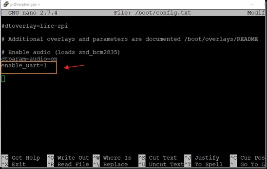
The GPIO serial port is disabled by default. In order to enable it, edit config.txt:
$ sudo nano /boot/config.txt
and add the line (at the bottom):
enable_uart=1
Reboot for the changes to take effect.
Restart the Putty SSH
Now check the cd /dev , ls –l again
You can see both the ports enabled. Note that this can be done through raspi-config also.
Let us connect the GSM with PI now.
The logic levels of PI are at 3.3 volts & it is risky to connect directly with a 5v level GSM pin.
The Tx pin (pin 8 , GPIO14) of PI can be directly connected to Rx of GSM. As GSM accepts 3.3volt level as high , this connection is straight without level shifting.
However the Rx pin (pin 10, GPIO 15) of PI cannot be connected directly to Tx of GSM.
A simple level shifter using a signal diode 1N4148 & a 10k resistor is used in between as shown below
LOGIC LEVEL SHIFTER
When the level at GSM Tx is LOW , the diode is forward biased & the Rx of PI gets LOW.
When the level at GSM Tx is HIGH ,the diode is Reverse biased & the 3.3v is available at Rx of PI through the resistor.
A separate power source 12v 1 amp is required for GSM , and the GND pins of PI & GSM are made common.
Be cautious while connecting with PI pins , as any wrong connection will render the PI defective.
After powering the GSM wait for the network. The network LED blinks fast initially & after getting Network it blinks slowly.
You can also call to the SIM number used on the GSM to get a ring back tone.
Now the set upis ready.
Let us install a Serial monitor called picocom on PI to test the AT commands.
Start the picocom with baud rate 9600 & at portttyS0
picocom –baud 9600 /dev/ttyS0
Note the double hyphen before baud .
You get Terminal Ready
after which you can type in AT to get an OK response.
If you cannot seewhat you type,or if no response then check the GSM for network &also check the port name you’ve typed.
It must be /dev/ttyS0 . S is capital letter & then zero.
Now you can make a call using ATDxxxxx; command , terminate a call using ATH
Send SMS using AT+CMGF=1 , & test other AT commands
Now let us use PYTHON to make a call.
Open a file named dial.py using
sudo nano dial.py
Type in following code & then CTRL+X , to exit & Yes to save.
While using AT command inside Python code , notice the usage of carriage return
\r after each command like ATDxxx; \r
To execute the file
python dial.py
You can see the number being called & then hangs up using ATH command.
Now let us create a python code for sending SMS.
Notice the usage of double quotes for sending AT commands
Also, note that single quotes used if the AT command needs to send double quotes
as in AT+CMGS command
To execute type in
python sms.py
You can see the sms being sent to the phone number used in code.


No hay comentarios:
Publicar un comentario