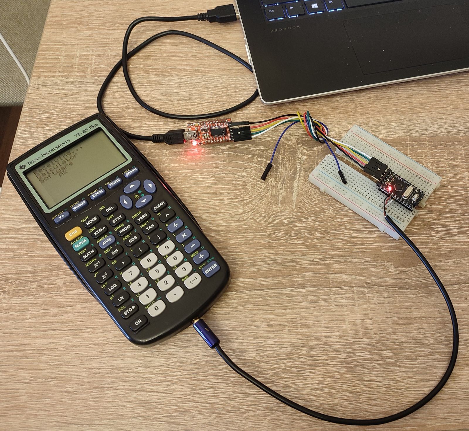
TRS Calculadoras Texas Ti83 comunicacion con Arduino half-duplex, arduino to TI 83+/84+, 86 Created by William Massano
https://www.nutsvolts.com/magazine/article/May2014_Massano
Calculators as Coprocessors
While microcontrollers have grown to be very powerful, sometimes you need math functions that are not available or graphic capabilities that are complex to program. The popular TI (Texas Instruments) series calculators (TI 83+, TI 84+, and TI 86) have these capabilities and are often found lying around the home unused. I was looking for such a device when I saw an article about interfacing a PIC microcontroller to a TI 83+.
While the article gave good basic information, I found it lacking on three counts. First, it was centered around a PIC and I needed the code for an Arduino. Second, the language utilized was Great Cow Basic; I needed C (and a more robust implementation that did not rely on global variables — a known problem with GCB). Finally, the code in the article was only a demonstration of its potential; I needed detailed routines. For example, I needed to send numbers in my code and didn’t want to be responsible for converting them to strings first. That is what computers are for!
My first thought was to look online to see if anyone had solved this issue before I attempted to reinvent the wheel. I was disappointed. The only C code I found was similar to the GCB implementation and poorly written (unless they were deliberately obfuscating the code). I would fail one of my students if they wrote code that declared variables in the middle of a program rather than at the start of the routine!
So, I have written my own code in the form of an Arduino library which is available with the article downloads. The code will automatically detect the calculator that is attached: TI 82, 83+, 84+, or 86. The TI 82 does not support silent transfer, so it’s not supported by my code at this time.
After startup, you may send or get any variable (A-Z on 83+/84+, the 86 supports longer names) via silent transfer, and you may send any TI command that the calculator accepts. List sending is also supported and, of course, data plotting.
For an excellent guide to the protocols, go to TI-73...V200 Link Protocol Guide v1.4 by Tim Singer and Romain Liévin at http://merthsoft.com/linkguide/ and choose the 83+ or 86. For the command codes, go to http://merthsoft.com/linkguide/ti83+/keys.txt or replace 83+ with 86 for those codes.
Protocol and Wiring
The original article I mentioned has a good description of the basic protocol, but I will summarize it here.
The TIs communicate over a serial two-line (+ground) communication link. The cable is a 2.5 mm (3/32") TRS cable. The tip of the connector is the Data0 line; the ring is the Data1 line; and the sleeve is ground. When idling, both lines are held high by the Arduino internal pull-up resistors.
To send a zero, the sender pulls the Data0 line low. The receiver then pulls the Data1 line low to acknowledge, then both lines go high. To send a one, the sender pulls the Data1 line low and the receiver acknowledges by pulling the Data0 line low. These are handled by the library's internal functions and don’t need to be accessed by the user directly.
Figure 1 shows a data cable that I made by buying a TRS cable on eBay and cutting it in half.
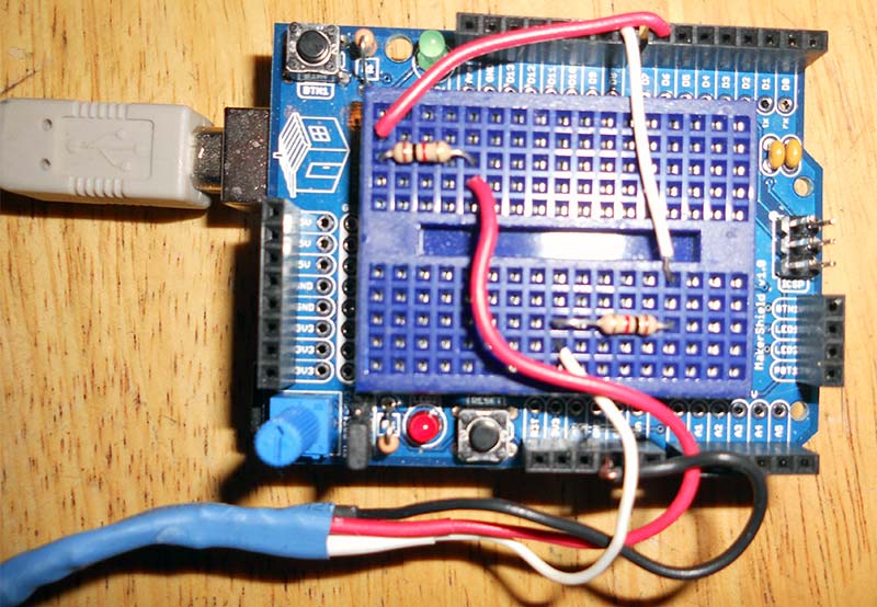
Figure 1. Wiring.
Finally, in my experience, the TI 83+ can’t handle the current drawn by a direct connection to the Arduino, so I put a 1K resistor in series with each data line; all calculators are happy with this arrangement. I connected these to two Arduino digital pins. Note the schematic in Figure 2.
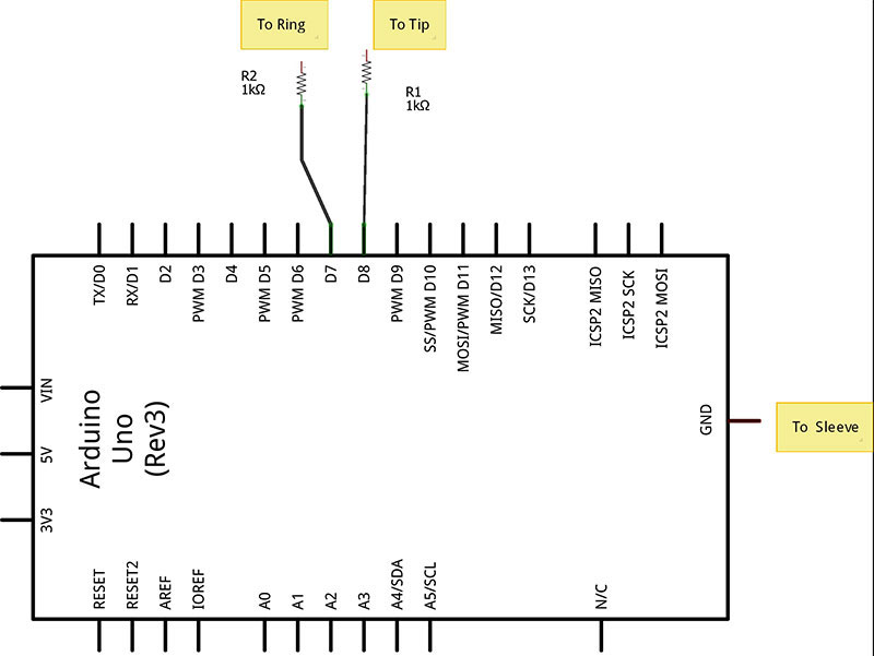
Figure 2. Schematic.
Using the Library
Copy the library folder ArtoTI to the Arduino library folder then insert #include <ArtoTI.h> into the code. Use the constructor before the setup function:
ArtoTI a(8,7);
where "a" is the name of the instance, 8 stands for the pin connected to the tip, and 7 stands for the pin connected to the sleeve. Once that’s done, you can call any public function (see ArtoTI.h or the guide included in the library folder for the available functions).
The first basic job handled by the library is to send and receive numbers to and from the calculator. TI calculators (at least the ones for which this library is written) use "silent transfer" which means that the calculator doesn’t have to be in a special mode to get or send numbers.
The two routines that handle the protocol are sendNum and getNum. Their use:
sendNum(memloc, doublenum);
x=getNum(memloc);
where memloc is a TI variable name — A-Z (as a string) for 83+/84+ and a string of one or more characters for the 86. Doublenum is a real number (double is the same as float for the Aduino Uno) and getNum returns a double. Note: The Arduino can handle 10^±38 but the calculators can handle 10^±99.
The other job is to send commands. Here, there are two problems. First, the 86 has different command codes to the 83+/84+ codes. Second, many are non-alphanumeric — the square root symbol, for example.
Here, there are two choices:
sendCmd(hexcode);
which sends a hex code (0x0005, for example). This always works but can get tedious. Some of the example programs at the article link show a sample. Next is:
sendANstring(command string);
which is a mini parser. It can handle text and a limited number of operators. Anything it doesn't recognize is not sent.
The mini parser is capable (at the time of this writing) of handling any single letter or operator like +, -, etc. It also allows for quoted commands. The percent sign "%" is the quote character. It’s followed by a two-letter command. (See the guide in the library folder for available commands).
To send something like sin(30) to the 83+/84+, you can use sendANstring("%SN30)"). The percent sign can be sent by typing %%. The 86 can recognize some strings without resorting to the tokens, but tokens will work as well. Tokens are not case sensitive.
The final choice is:
sendOP(opchar);
It can send the operators plus some special ones like Pi, the EE key, and a few others. Again, anything not found here can be sent by using sendCmd. This option is not recommended and may be eliminated. Use sendANstring instead.
I didn’t make the parser complete because the library is already over 16K if fully used, which is about half the Uno's code space. If you need more, you can easily modify the library.
A few other routines are Enter() to send the "enter" key; clearScreen(); getDir() which gets a directory of the variables stores in the calculator and prints them to the serial monitor; and getStatus() which gets the status (and identity) of the calculator.
Finally, floatout corrects a defect in the Serial.print routine to handle floating point numbers correctly; comp holds the code used by the computer to send instructions and helps distinguish between the 86 and the 83+/84+ which use the same code.
Graphic commands can usually be sent by sendANstring or sendCmd if needed, or a combination of both — one of the examples at the article link shows this.
Plotting can be done via the Plot command. Lists can be sent as well, so statistics may be processed on them.
There are six example programs included in the available library. The first shows how to use the constructor (see Figure 3).
/* arduino to TI 83+/84+, 86
Example 1
Created by William Massano
Initialize instance and see what is connected
*/
#include <ArtoTI.h>
ArtoTI calc(8,7);
void setup(void){
Serial.begin(9600);
Serial.println("Start:");
pinMode(13,OUTPUT);
digitalWrite(13,LOW); //for some reason 13 is high, force it low
if(calc.comp==0){
Serial.println("Calculator not recognized, aborting");
return;
}
Serial.print("Calculator type:");
if(calc.calctype<0){
Serial.println(abs(calc.calctype));
}else{
switch (calc.calctype){
case 83:
case 84: Serial.print(calc.calctype);
Serial.println("+");
break;
case 82:
case 86: Serial.println(calc.calctype);
break;
}
}
Serial.println("Done");
}
void loop(){
}
Figure 3. Example 1: Identifying the calculator.
There are examples of sending data and calculating math, as well as a demo of some of the functions. The last examples (5 and 6) draw a circle and plot data (Y vs X where Y=X^2).
Figure 4 is a screenshot of the plot (y=x^2) from example 6.
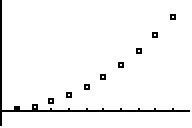
Figure 4. Plot screenshot.
The code that produced it is in Figure 5.
/* arduino to TI 83+/84+, 86
Example 6
Created by William Massano
create 2 lists and plot them in an x-y plot
example does 10 points, but you can do more
*/
#include <ArtoTI.h>
ArtoTI calc(8,7);
void setup(void){
double list1[20],list2[20];
int i;
Serial.begin(9600);
Serial.println("Start:");
pinMode(13,OUTPUT);
digitalWrite(13,LOW); //for some reason 13 is high, force it low
if(calc.comp==0){
Serial.println("Calculator not recognized, aborting");
return;
}
for(i=0;i<20;i++){
list1[i]=1+i;
list2[i]=list1[i]*list1[i];
}
calc.Plot(list1, list2, 10,0); //plot with box marks
delay(5000);
calc.clearScreen();
calc.clearScreen();
Serial.println("Done");
}
void loop(){
}
Figure 5. Example 6 code.
The final example (7) shows a case where two calculators are controlled at the same time (you can control as many calculators as you have pins for). Since this is really C++, we can create two instances of ArtoTI and deal with each instance separately.
Obviously, you need two each of calculators, cables, and resistors, but at least you know that if you need this feature it’s available.
For improvements, the parser can be expanded, and lists can be sent via silent transfer. Currently, I can’t get it to work, so they are sent as keystrokes. If anyone can send the lists silently, I’d like to see the protocol they’re using. Finally, I’m considering adding the 89.
I hope this library allows people to make use of these fine calculators in a new way! NV
 download