http://www.youtube.com/watch?v=-DM6Y66-B9c&list=PLtBJnLlwfWwL1uc_dc_JhPacD_1qqNsOX&index=1
sábado, 21 de junio de 2014
Buena Musica Champeta Clasica
Buena Lista de champeta Clasica
http://www.youtube.com/watch?v=-DM6Y66-B9c&list=PLtBJnLlwfWwL1uc_dc_JhPacD_1qqNsOX&index=1
http://www.youtube.com/watch?v=-DM6Y66-B9c&list=PLtBJnLlwfWwL1uc_dc_JhPacD_1qqNsOX&index=1

Editor de Ecuaciones online a jpeg
http://rinconmatematico.com/latexrender/
Este programa te permite practicar lo básico del código LaTeX, mostrándote en tiempo real el aspecto gráfico que tomarán tus expresiones.
Entra el código y luego aprieta "Mostrar Fórmula". Los íconos son solamente una pequeña muestra de las cosas que puedes hacer. Al hacer clic en uno o más iconos verás el código LaTeX , al que podrás añadir las variaciones que desees.
Advierte que el comando \displaystyle puede ser antepuesto a ciertos comandos, obteniendo una fórmula algo más grande y con mejor aspecto: haz la prueba con fracciones, integrales, sumatorias, intersecciones generalizadas, etc.
Advertencias
Este programa te permite practicar lo básico del código LaTeX, mostrándote en tiempo real el aspecto gráfico que tomarán tus expresiones.
Entra el código y luego aprieta "Mostrar Fórmula". Los íconos son solamente una pequeña muestra de las cosas que puedes hacer. Al hacer clic en uno o más iconos verás el código LaTeX , al que podrás añadir las variaciones que desees.
Advierte que el comando \displaystyle puede ser antepuesto a ciertos comandos, obteniendo una fórmula algo más grande y con mejor aspecto: haz la prueba con fracciones, integrales, sumatorias, intersecciones generalizadas, etc.
Advertencias
- A diferencia de lo que ocurre en los foros, acá no es preciso que encierres las fórmulas entre [tex] y [/tex].
- A diferencia de lo que ocurre en los editores habituales de LaTeX, acá no es es preciso que encierres las fórmulas entre $ y $.
- La carpeta de fórmulas de este editor se vacía con frecuencia, de modo que si enlazas una fórmula a este editor, más temprano que tarde tu fórmula desaparecerá.
Ecuaciones en Latex a jpeg online
Una vez ingrese la ecuación le da click derecho a la imagen de la ecuación y la guarda donde quiera
http://www.codecogs.com/latex/eqneditor.php
Ejemplo
http://www.codecogs.com/latex/eqneditor.php
Ejemplo
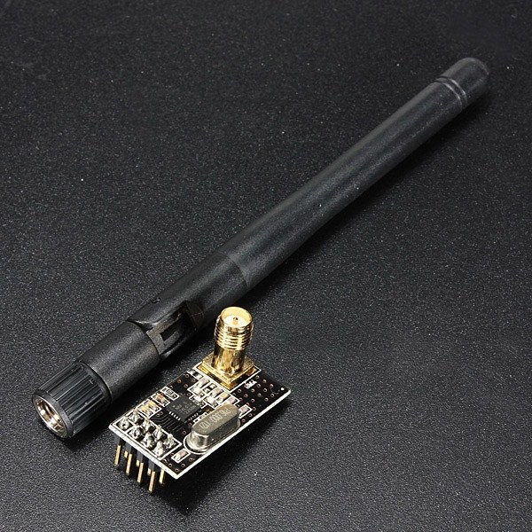
Módulo Transceptor RF nRF24L01+ 2.4 Ghz con Antena SMA Librerias Tutorial Arduino
- Esquema
- nRF24L01 Datasheet
- Great Nordic tutorials
- Ejemplo en mbed
- Tutorial para Arduino
- RF24 librería y ejemplos
- RF24 Red de Información de Sistema
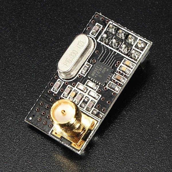
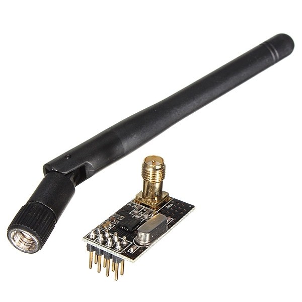
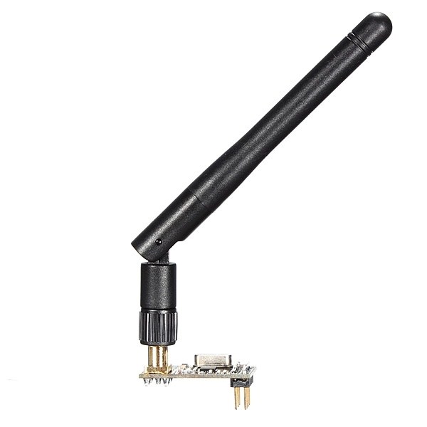
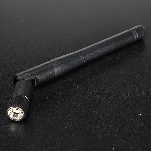
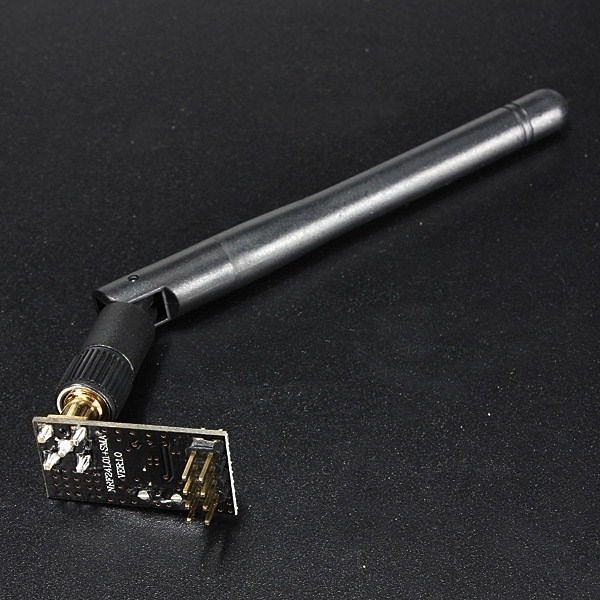
Módulo Transceptor RF nRF24L01+ 2.4 Ghz con Antena SMA
Descripción del Producto
Este módulo usa un nuevo transceptor de la compañía Nordic Semiconductor, el nRF24L01+.Este transceptor opera en la banda de 2.4GHz y tiene muchas características nuevas. Es similar al nRF2401+ e incorpora adicionalmente extra pipelines, buffers, y un modo de auto retransmisión.
El módulo utiliza 8 pines para su interfaz externa y funciona con el estándar de comunicación SPI.

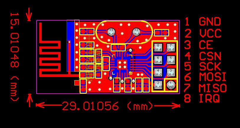
Pines nRF24L01+. Click para ampliar.
Características
- Voltaje de alimentación de 1.9 a 3.6V
- Banda ISM de 2.4GHz
- Velocidad de datos de hasta 2Mbps.
- Operación a muy baja potencia.
- 11.3mA TX a 0dBm de potencia de salida
- 12.3mA RX a una velocidad de datos de 2Mbps
- 900nA estando apagado
- 22μA en espera-I
- ShockBurst™ Mejorado
- Compatible con nRF2401A, 02, E1 y E2
- Distancia de alcance de hasta 1000mts en línea de vista
Mas información:
Modulo Transceptor Rf Nrf24l01 + Antena , Arduino
http://articulo.mercadolibre.com.co/MCO-410996175-modulo-transceptor-rf-nrf24l01-antena-arduino-pic-24-ghz-_JM#
http://maniacbug.wordpress.com/2011/11/02/getting-started-rf24/
Nordic’s nRF24L01+ 2.4GHz RF radios are a great way to communicate
wirelessly between Arduino’s. They’re cheap, and powerful.
Unfortunately, they can be a little daunting to beginners to get
started. Today, I want to make it easy for total beginners to get up
and running on nRF24L01+ radios quickly and easily.
Here’s what it looks like all ready to go. Click on the picture for a closer view. In this picture, I am using a pair of 4-pin female headers instead of a 2×4 female header. I also cut an extra green wire I decided not to use in this tutorial.
Here’s what it looks like with all the wires in place, up close and personal. Again, click through for even bigger images.
From the File menu, select “Examples”, then “RF24″, and finally “GettingStarted”. This will load up the GettingStarted example. It looks something like this. Take a look at the GettingStarted example in the documentation for all the details.
Upload the sketch, start the serial monitor, set the speed to 57600, and you should see this:
Instead, if you see a lot of zeroes everywhere, something is wrong
with your connections. Double check them all again! In the course of
making this tutorial, I even switched two of the wires myself and had to
re-solder them. If you hooked everything else up right, you will see
numbers just like those above.
Start the second unit up, just like above, and launch the serial monitor at 57600. Press the ‘T’ key once the debugging text has printed successfully. That will put this unit into Transmit mode, which sends a ping out to the other unit. Make sure the other unit is still running, so this one has something to talk to!
Soon you will see the happy chatter of the radios doing their thing:
Instead of the ghetto-style ProtoBoard setup, you could step it up a notch and use a Arduino ProtoShield Kit. See the more recent post, Getting Started with nRF24L01+ using a Protoshield
In a future post, I’ll put up a simple PCB you could use instead of all the soldering. It’ll be a little smaller, too.
http://maniacbug.wordpress.com/2011/11/02/getting-started-rf24/

Getting Started with nRF24L01+ on Arduino

Stuff we need
First, we have to go shopping. A great place to start is the iTeadStudio store. Here’s what you need. Obviously, you’ll want to buy two of the radios and protoboards because what good is a radio that can only talk to itself?- 2.4G Wireless nRF24L01+ Module $4.00
- 2.54mm 2x4Pin Female Header (5Pcs) $1.50
- 2.54mm 40Pin Male Header (5 Psc) $1.50
- Double Side ProtoBoard 5cm * 7cm $0.99
- Solder cable – 7cm (10pcs) $0.50 (Or get some wire at Home Depot and cut it yourself)
Preparation
We only need one of the 2×4 pin female headers. Cut off two chunks of the male headers, lengths of 6 and 8 pins. Cut wires to about 2inches in length. If you use the 7cm wires from iTeadStudio, it’s OK, you’ll just have a little extra wire in the way.Here’s what it looks like all ready to go. Click on the picture for a closer view. In this picture, I am using a pair of 4-pin female headers instead of a 2×4 female header. I also cut an extra green wire I decided not to use in this tutorial.

Solder it up
- The 8-pin male header goes in position C09-16.
- The 6-pin male header goes in position V13-18.
- The 2×4-pin male header goes in position K16-N15.
- The wires are connected as follows:
| Line | From Arduino Pin | From Grid Position | To Radio Pin | To Grid Position |
| GND | GND | U17 | 1 | N17 |
| 3V3 | 3V3 | U14 | 2 | N14 |
| CE | 9 | D15 | 3 | M17 |
| CSN | 10 | D14 | 4 | M14 |
| SCK | 13 | D11 | 5 | L17 |
| MOSI | 11 | D13 | 6 | L14 |
| MISO | 12 | D12 | 7 | K16 |

Software
Get the RF24 library from github. There is ample documentation at that link, as well as a pointer to the downloads page. Unzip the archive in to your ‘libraries’ folder under your sketch folder (mine is in /home/users/maniacbug/Source/Arduino/libraries), and restart the Arduino IDE.From the File menu, select “Examples”, then “RF24″, and finally “GettingStarted”. This will load up the GettingStarted example. It looks something like this. Take a look at the GettingStarted example in the documentation for all the details.
/**
 * Example for Getting Started with nRF24L01+ radios.
 *
 * This is an example of how to use the RF24 class.  Write this sketch to two
 * different nodes.  Put one of the nodes into 'transmit' mode by connecting
 * with the serial monitor and sending a 'T'.  The ping node sends the current
 * time to the pong node, which responds by sending the value back.  The ping
 * node can then see how long the whole cycle took.
 */

#include <SPI.h>
#include "nRF24L01.h"
#include "RF24.h"
#include "printf.h"

//
// Hardware configuration
//

// Set up nRF24L01 radio on SPI bus plus pins 9 & 10

RF24 radio(9,10);RF24/examples/GettingStarted/
ROLE: Pong back
STATUS = 0x0e RX_DR=0 TX_DS=0 MAX_RT=0 RX_P_NO=7 TX_FULL=0
RX_ADDR_P0-1 = 0xf0f0f0f0d2 0xf0f0f0f0e1
RX_ADDR_P2-5 = 0xc3 0xc4 0xc5 0xc6
TX_ADDR = 0xf0f0f0f0d2
RX_PW_P0-6 = 0x08 0x08 0x00 0x00 0x00 0x00
EN_AA = 0x3f
EN_RXADDR = 0x03
RF_CH = 0x4c
RF_SETUP = 0x07
CONFIG = 0x0f
DYNPD/FEATURE = 0x00 0x00
Data Rate = 1MBPS
Model = nRF24L01
CRC Length = 16 bits
PA Power = PA_HIGHMake another one
Ok, do it all again, making another protoboard shield, on top of another Arduino, so our first unit has something to talk to.Start the second unit up, just like above, and launch the serial monitor at 57600. Press the ‘T’ key once the debugging text has printed successfully. That will put this unit into Transmit mode, which sends a ping out to the other unit. Make sure the other unit is still running, so this one has something to talk to!
Soon you will see the happy chatter of the radios doing their thing:
Now sending 90...ok...Got response 90, round-trip delay: 28
Now sending 1122...ok...Got response 1122, round-trip delay: 26
Now sending 2152...ok...Got response 2152, round-trip delay: 27
Now sending 3182...ok...Got response 3182, round-trip delay: 29
Now sending 4214...ok...Got response 4214, round-trip delay: 27
Now sending 5244...ok...Got response 5244, round-trip delay: 29
Now sending 6277...ok...Got response 6277, round-trip delay: 26
Now sending 7307...ok...Got response 7307, round-trip delay: 26
Now sending 8337...ok...Got response 8337, round-trip delay: 29
Now sending 9369...ok...Got response 9369, round-trip delay: 27
Now sending 10399...ok...Got response 10399, round-trip delay: 29
Now sending 11431...ok...Got response 11431, round-trip delay: 27
Now sending 12462...ok...Got response 12462, round-trip delay: 28
From here…
The examples directory in the RF24 library has all sorts of different things you can try. If you’re feeling adventurous, you can even hook up the IRQ pin from pin 8 on the radio to pin 2 on the Arduino (that was what the extra green wire was for in my ‘parts’ picture).Instead of the ghetto-style ProtoBoard setup, you could step it up a notch and use a Arduino ProtoShield Kit. See the more recent post, Getting Started with nRF24L01+ using a Protoshield
In a future post, I’ll put up a simple PCB you could use instead of all the soldering. It’ll be a little smaller, too.
viernes, 20 de junio de 2014


Suscribirse a:
Entradas (Atom)