Transformer less AC to DC power supply circuit using dropping capacitor
http://www.circuitsgallery.com/2012/07/transformer-less-ac-to-dc-capacitor-power-supply-circuit2.html
Production of low voltage DC power supply from AC power is the most important problem faced by many electronics developers and hobbyists. The straight forward technique is the use of a step down transformer to reduce the 230 V or 110V AC to a preferred level of low voltage AC. But i-St@r comes with the most appropriate method to create a low cost power supply by avoiding the use of bulky transformer.Yes, you can construct power supply for your development without a transformer. This circuit is so simple and it uses a voltage dropping capacitor in series with the phase line. Transformer less power supply is also called as capacitor power supply. It can generate 5V, 6V, 12V 150mA from 230V or 110V AC by using appropriate zener diodes. See the design below.
Circuit diagram

Components required
- Resistors (470kΩ, 1W; 100Ω)
- Capacitors (2.2µF, 400V, X rated; 1000µF, 50V)
- Bridge rectifier (1N4007 diodes x 4)
- Zener diode (6.2V, 1W)
- LED (Optional)
Working of Transformer less capacitor power supply
- This transformer less power supply circuit is also named as capacitor power supply since it uses a special type of AC capacitor in series with the main power line.
- A common capacitor will not do the work because the mains spikes will generate holes in the dielectric and the capacitor will be cracked by passing of current from the mains through the capacitor.
- X rated capacitor suitable for the use in AC mains is vital for reducing AC voltage.
- A X rated dropping capacitor is intended for 250V, 400V, 600V AC. Higher voltage versions are also obtainable. The dropping capacitor is non polarized so that it can be connected any way in the circuit.
- The 470kΩ resistor is a bleeder resistor that removes the stored current from the capacitor when the circuit is unplugged. It avoid the possibility of electric shock.
- Reduced AC voltage is rectifiered by bridge rectifier circuit. We have already discussed about bridge rectifiers. Then the ripples are removed by the 1000µF capacitor.
- This circuit provides 24 volts at 160 mA current at the output. This 24 volt DC can be regulated to necessary output voltage using an appropriate 1 watt or above zener diode.
- Here we are using 6.2V zener. You can use any type of zener diode in order to get the required output voltage.
Design
Reactance of the capacitor, where f is the supply frequency and C is the capacitance.
If the supply frequency is 50Hz, then reactance of 2.2µF X rated capacitor is given by,

So output current,

You can design your own supply if you need high current rating other than 159mA by choosing different capacitor values.
Calculating Capacitor Current in Transformerless Power Supplies
https://www.homemade-circuits.com/calculating-capacitor-current-in/You may have studied countless transformerless power supplies in this blog and in the web, however calculating the crucial mains capacitor current in such circuits has always remained an issue for the many constructors.
Analyzing a Capactive Power Supply
Before we learn the formula for calculating and optimizing the mains capacitor current in a transformerless power supply, it would be important to first summarize a standard transformerless power supply design.The following diagram shows a classic transformerless power supply design:
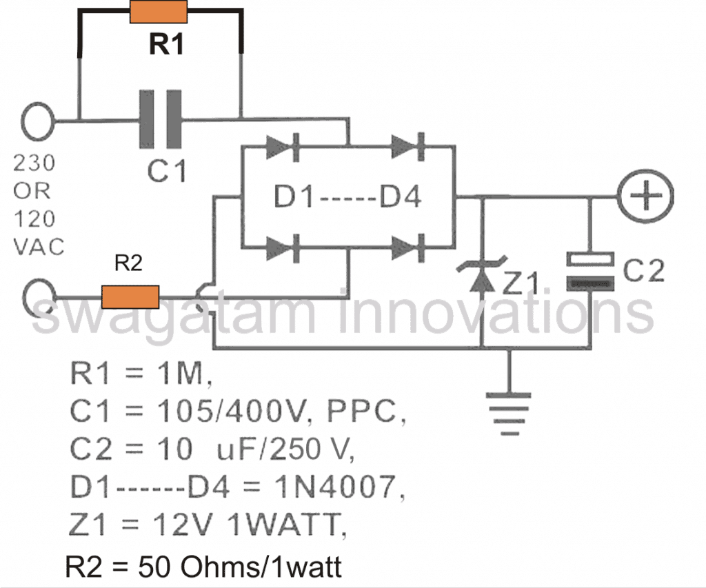
Referring to the diagram, the various components involved are assigned with the following specific functions:
C1 is the nonopolar high voltage capacitor which is introduced for dropping the lethal mains current to the desired limits as per the load specification. This component thus becomes extremely crucial due to the assigned mains current limiting function.
D1 to D4 are configured as a bridge rectifier network for rectifying the stepped down AC from C1, in order to make the output suitable to any intended DC load.
Z1 is positioned for stabilizing the output to the required safe voltage limits.
C2 is installed to filter out any ripple in the DC and to create a perfectly clean DC for the connected load.
R2 may be optional but is recommended for tackling a switch ON surge from mains, although preferably this component must be replaced with a NTC thermistor.
Capacitor Controls Current
In the entire transformerless design discussed above, C1 is the one crucial component which must be dimensioned correctly so that the current output from it is optimized optimally as per the load specification.Selecting a high value capacitor for a relatively smaller load may increase the risk of excessive surge current entering the load and damaging it sooner.
A properly calculated capacitor on the contrary ensures a controlled surge inrush and nominal dissipation maintaining adequate safety for the connected load.
Using Ohm's Law
The magnitude of current that may be optimally permissible through a transformerless power supply for a particular load may be calculated by using Ohm's law:I = V/R
where I = current, V = Voltage, R = Resistance
However as we can see, in the above formula R is an odd parameter since we are dealing with a capacitor as the current limiting member.
In order to crack this we need to derive a method which will translate the capacitor's current limiting value in terms of Ohms or resistance unit, so that the Ohm's law formula could be solved.
Calculating Capacitor Reactance
To do this we first find out the reactance of the capacitor which may be considered as the resistance equivalent of a resistor.The formula for reactance is:
Xc = 1/2(pi) fC
where Xc = reactance,
pi = 22/7
f = frequency
C = capacitor value in Farads
The result obtained from the above formula is in Ohms which can be directly substituted in our previously mentioned Ohm's law.
Let's solve an example for understanding the implementation of the above formulas:
Let's see how much current a 1uF capacitor can deliver to a particular load:
We have the following data in our hand:
pi = 22/7 = 3.14
f = 50 Hz (mains AC frequency)
and C= 1uF or 0.000001F
Solving the reactance equation using the above data gives:
Xc = 1 / (2 x 3.14 x 50 x 0.000001)
= 3184 ohms approximately
Substituting this equivalent resistance value in our Ohm's law formula, we get:
R = V/I
or I = V/R
Assuming V = 220V (since the capacitor is intended to work with the mains voltage.)
We get:
I = 220/3184
= 0.069 amps or 69 mA approximately
Similarly other capacitors can be calculated for knowing their maximum current delivering capacity or rating.
The above discussion comprehensively explains how a capacitor current may be calculated in any relevant circuit, particularly in transformerless capacitive power supplies.
https://circuitdigest.com/electronic-circuits/transformerless-power-supply
X-Rated Capacitor
As mentioned they are connected in series with
phase line of AC to lower down the voltage, they are available in 230v,
400v, 600v AC or higher ratings.
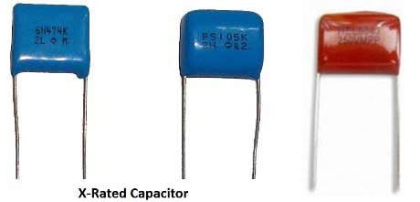
Below is the table for output current and output voltage (without the Load), of different values of X-rated capacitors:
|
Capacitor Code
|
Capacitor value
|
Voltage
|
Current
|
|
104k
|
0.1 uF
|
4 v
|
8 mA
|
|
334k
|
0.33 uF
|
10 v
|
22 mA
|
|
474k
|
0.47 uF
|
12 v
|
25 mA
|
|
684k
|
0.68 uF
|
18 v
|
100 mA
|
|
105k
|
1 uF
|
24 v
|
40 mA
|
|
225k
|
2.2 uF
|
24 v
|
100 mA
|
Selection of voltage dropping capacitor is
important, it is based on Reactance of Capacitor and the amount of
current to be withdrawn. The Reactance of the capacitor is given by
below formula:
X = 1 / 2¶fC
X = Reactance of Capacitor
f = frequency of AC
C = Capacitance of X rated capacitor
We have used 474k means 0.47uF capacitor and frequency of AV mains is 50 Hz so the Reactance X is:
X = 1 / 2*3.14*50*0.47*10-6 = 6776 ohm (approx)
Now we can calculate the current (I) in the circuit:
I = V/X = 230/6775 = 34mA
So that’s how the Reactance and Current is calculated.


