How to Build an Inexpensive Frequency Meter and a Capacitance Meter at Home
Capacitors are one of the major electronic components which
come under the passive component family. These are extensively used in
lectronic circuits and virtually no circuit can be built without involving these
important parts.
However unlike resistors, capacitors are difficult to measure through ordinary methods. For example, an ordinary multitester might have many measuring features included like an OHM meter, voltmeter, ammeter, diode tester, hFE tester etc. but might just not have the illusive capacitance measuring feature.


The basic function of a capacitor is to block DC and pass AC
or in simple words any voltage which is pulsating in nature will be allowed to
pass through a capacitor and any voltage that’s not polarized or direct will be
blocked by a capacitor by the process of charging.
However unlike resistors, capacitors are difficult to measure through ordinary methods. For example, an ordinary multitester might have many measuring features included like an OHM meter, voltmeter, ammeter, diode tester, hFE tester etc. but might just not have the illusive capacitance measuring feature.
The feature of a capacitance meter or an inductance meter is
seen to be available only in high end type of multimeters which are definitely
not cheap and not every new hobbyist might be interested in procuring one.
The circuit discussed here very effectively tackles these
issues and shows how to build a simple inexpensive capacitance cum frequency meter
which can be built at home by any electronic novice and used for the intended
useful application.


Circuit Description:
Referring to the figure, the IC 555 forms the heart of the
entire configuration. This work horse versatile chip is configured in its most
standard mode that is the monostable multivibrator mode.
Every positive peak of the pulse applied at the input that
is pin #2 of the IC creates a stable output with some predetermined fixed
period set by the preset P1.
However for every fall in the peak of the pulse, the
monostable resets and auto triggers with the next arriving peak.
This generates a kind of an average value at the output of
the IC for which is directly proportional to the frequency of the applied
clock. In other words the output of the IC 555 which consists of a few
resistors and capacitors integrates the series of pulses to provide a stable
average value directly proportional to the applied frequency.
The average value can be easily read or displayed over a
moving coil meter connected across the shown points.
So the above reading will give a direct reading of the
frequency, so we have a neat looking frequency meter at our disposal.
Now looking at the next figure we can clearly see that by adding
an external frequency generator to the previous circuit, it becomes possible to
make the meter interpret the values of a capacitor across the indicated points,
because this capacitor directly affects or is proportional to the frequency of
the clock circuit.
Therefore, the net frequency value now shown at the output
will correspond to the value of the capacitor connected across the above
discussed points.
That means now we have a two in one circuit which can
measure capacitance as well as frequency, using just a couple of ICs and some
casual electronic parts.
With little modifications the circuit can be easily used as
a tachometer or as RPM counter equipment.
Parts List
R1 = 4K7
R2 = 47E
R3 = CAN BE VARIABLE 100K POT
R4 = 3K3,
R5 = 10K,
R6 = 1K,
R7 1K,
R8 = 10K,
R9 = 100K,
C1 = 47n,
C2 = 100n,
C3 = 100n,
C4 = 33uF/25V,
T1 = BC547
IC1 = 555,
N1---N6 = IC4049
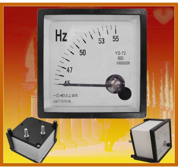
M1 = 1V FSD meter,
D1,D2 = 1N4148
////////////////////////////////
Build a Versatile Frequency Meter For Your Workbench
Introduction
The frequency meters available in the market are generally too costly and sophisticated. For new electronic enthusiasts it is always difficult to lay their hands on these hi-end types of frequency meters. Also, since the measuring needs of these electronic novices are limited, a simple analogue frequency meter in most cases can easily fulfill their demands. The homemade frequency meter circuit described in this article is very simple in design and will provide an optimum frequency measuring range useful to most electronic hobbyists. Moreover it would be great fun to build a test instrument at home and use it for the testing purposes of the future construction projects.What is Frequency?
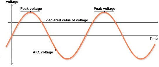
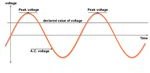 In electronics, a frequency generally is in the form of a voltage that changes or varies its polarity number of times per second. You may take the example of your domestic mains AC line where the frequency of the voltage changes from positive to negative 50 to 60 times a second, hence the name Alternating Current or AC.The frequencies involved in electronic circuits are always low in magnitude and may not exceed the maximum operating voltage or the supply voltage of the circuit itself. These are used to fulfill many complicated functions in a circuit and are mostly generated using CMOS logic gates. It often becomes necessary to measure the rate of these frequencies and thus a frequency meter proves to be quite an indispensable tool for it.The circuit of an analogue frequency meter presented here can be used to measure frequencies from as low as 25 Hz to a maximum of 500 KHz.
Circuit Description
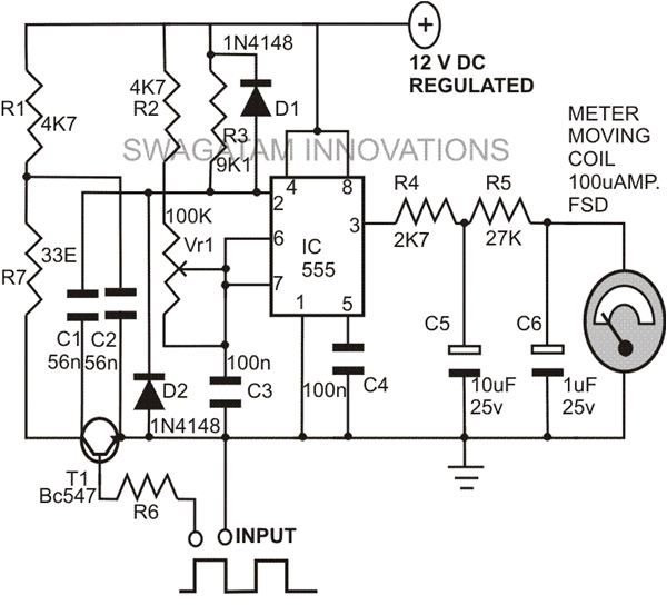
 To understand the circuit functioning of this homemade frequency meter, let’s go through the following explanation:
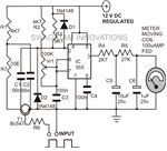 IC 555 forms the main part of the circuit and is wired as a monostable multivibrator.Its frequency is determined by the external components R2, VR1 and C3. The setting of VR1 is important and may be used to adjust the measuring range of the frequency meter.The frequency in question is applied to the base of transistor T1 via resistor R6. T1 conducts only during the positive peaks of the input oscillations.During these conductions of T1, capacitor C2 is forced to discharge quickly through R7 and T1. Also, during the negative peaks of the input oscillations, T1 is cut OFF and now C2 charges via R1 but at a fairly slow rate.Due to this, a sharp negative pulse appears at pin 2 of the IC through the capacitor C1. Resistor R3 makes it sure that the pulse is narrow and only just triggers the IC.The IC immediately responds to the trigger generating a pulse of a constant period set by VR1 at its output pin 3.This pulse is smoothed and integrated by R4, R5 and C5, C6 to produce an average value of the pulses. A moving coil type meter can be used to indicate this integrated value.The magnitude of these pulses will linearly vary with the input frequency and thus can be directly measured over the meter.Waveform Image Credit: http://www.bbc.co.uk/scotland/learning/bitesize/standard/physics/images/waveform2.gif
No hay comentarios:
Publicar un comentario