lunes, 3 de abril de 2017

Transitorio analisis en el tiempo Transient Circuits RL RC RLC Differential equations solution step by step very nice solution

Transitorio analisis en el tiempo Transient Circuits RL RC RLC Differential equations solution step by step very nice solution
http://www.intmath.com/differential-equations/5-rl-circuits.php

Application of Ordinary Differential Equations: Series RL Circuit
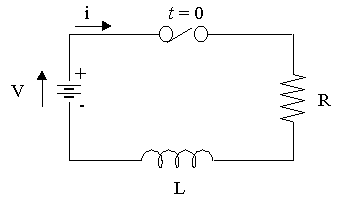
Series RL circuit diagram
RL circuit diagram
The RL circuit shown above has a resistor and an inductor connected in series. A constant voltage V is applied when the switch is closed.
The (variable) voltage across the resistor is given by:
VR=iR\displaystyle{V}_{{R}}={i}{R}VR=iR
The (variable) voltage across the inductor is given by:
VL=Ldidt\displaystyle{V}_{{L}}={L}\frac{{{d}{i}}}{{{\left.{d}{t}\right.}}}VL=Ldtdi
Kirchhoff's voltage law says that the directed sum of the voltages around a circuit must be zero. This results in the following differential equation:
Ri+Ldidt=V\displaystyle{R}{i}+{L}\frac{{{d}{i}}}{{{\left.{d}{t}\right.}}}={V}Ri+Ldtdi=V
Once the switch is closed, the current in the circuit is not constant. Instead, it will build up from zero to some steady state.
Continues below

Solving the DE for a Series RL Circuit

The solution of the differential equation Ri+Ldidt=V\displaystyle{R}{i}+{L}\frac{{{d}{i}}}{{{\left.{d}{t}\right.}}}={V}Ri+Ldtdi=V is:
i=VR(1e(R/L)t)\displaystyle{i}=\frac{V}{{R}}{\left({1}-{e}^{{-{\left({R}\text{/}{L}\right)}{t}}}\right)}i=RV(1e(R/L)t)
We start with:
Ri+Ldidt=V\displaystyle{R}{i}+{L}\frac{{{d}{i}}}{{{\left.{d}{t}\right.}}}={V}Ri+Ldtdi=V
Subtracting Ri from both sides:
Ldidt=VRi\displaystyle{L}\frac{{{d}{i}}}{{{\left.{d}{t}\right.}}}={V}-{R}{i}Ldtdi=VRi
Divide both sides by L:
didt=VRiL\displaystyle\frac{{{d}{i}}}{{{\left.{d}{t}\right.}}}=\frac{{{V}-{R}{i}}}{{L}}dtdi=LVRi
Multiply both sides by dt and divide both by (V - Ri):
diVRi=dtL\displaystyle\frac{{{d}{i}}}{{{V}-{R}{i}}}=\frac{{{\left.{d}{t}\right.}}}{{L}}VRidi=Ldt
Integrate (see Integration: Basic Logarithm Form):
diVRi=dtL\displaystyle\int\frac{{{d}{i}}}{{{V}-{R}{i}}}=\int\frac{{{\left.{d}{t}\right.}}}{{L}}VRidi=Ldt
ln(VRi)R=1Lt+K\displaystyle-\frac{{ \ln{{\left({V}-{R}{i}\right)}}}}{{R}}=\frac{1}{{L}}{t}+{K}Rln(VRi)=L1t+K
Now, since i=0\displaystyle{i}={0}i=0 when t=0\displaystyle{t}={0}t=0, we have:
K=ln VR\displaystyle{K}=-\frac{{ \ln{\ }{V}}}{{R}}K=Rln V
Substituting K back into our expression:
ln(VRi)R=1LtlnVR\displaystyle-\frac{{ \ln{{\left({V}-{R}{i}\right)}}}}{{R}}=\frac{1}{{L}}{t}-\frac{{ \ln{{V}}}}{{R}}Rln(VRi)=L1tRlnV
Rearranging:
ln VRln(VRi)R=1Lt\displaystyle\frac{{ \ln{\ }{V}}}{{R}}-\frac{{ \ln{{\left({V}-{R}{i}\right)}}}}{{R}}=\frac{1}{{L}}{t}Rln VRln(VRi)=L1t
Multiplying throughout by -R:
ln V+ln(VRi)=RLt\displaystyle- \ln{\ }{V}+ \ln{{\left({V}-{R}{i}\right)}}=-\frac{R}{{L}}{t}ln V+ln(VRi)=LRt
Collecting the logarithm parts together:
ln(VRiV)=RLt\displaystyle \ln{{\left(\frac{{{V}-{R}{i}}}{{V}}\right)}}=-\frac{R}{{L}}{t}ln(VVRi)=LRt
Taking "e to both sides":
VRiV=e(R/L)t\displaystyle\frac{{{V}-{R}{i}}}{{V}}={e}^{{-{\left({R}\text{/}{L}\right)}{t}}}VVRi=e(R/L)t
1RVi=e(R/L)t\displaystyle{1}-\frac{R}{{V}}{i}={e}^{{-{\left({R}\text{/}{L}\right)}{t}}}1VRi=e(R/L)t
Subtracting 1 from both sides:
RVi=1+e(R/L)t\displaystyle-\frac{R}{{V}}{i}=-{1}+{e}^{{-{\left({R}\text{/}{L}\right)}{t}}}VRi=1+e(R/L)t
Multiplying both sides by (VR)\displaystyle-{\left(\frac{V}{{R}}\right)}(RV):
i=VR(1e(R/L)t)\displaystyle{i}=\frac{V}{{R}}{\left({1}-{e}^{{-{\left({R}\text{/}{L}\right)}{t}}}\right)}i=RV(1e(R/L)t)
Please support IntMath!
[We did the same problem but with particular values back in section 2. Separation of Variables]
Here is the graph of this equation:
t i τ
VR\displaystyle\frac{V}{{R}}RV
Graph of i=VR(1e(R/L)t)\displaystyle{i}=\frac{V}{{R}}{\left({1}-{e}^{{-{\left({R}\text{/}{L}\right)}{t}}}\right)}i=RV(1e(R/L)t).
The plot shows the transition period during which the current adjusts from its initial value of zero to the final value VR\displaystyle\frac{V}{{R}}RV, which is the steady state.

The Time Constant

The time constant (TC), known as τ, of the function
i=VR(1e(R/L)t)\displaystyle{i}=\frac{V}{{R}}{\left({1}-{e}^{{-{\left({R}\text{/}{L}\right)}{t}}}\right)}i=RV(1e(R/L)t)
is the time at which RL\displaystyle\frac{R}{{L}}LR is unity ( = 1). Thus for the RL transient, the time constant is τ=LR\displaystyle\tau=\frac{L}{{R}}τ=RL seconds.
NOTE: τ is the Greek letter "tau" and is not the same as T or the time variable t, even though it looks very similar.
At 1 τ
1e(R/L)t\displaystyle{1}-{e}^{{-{\left({R}\text{/}{L}\right)}{t}}}1e(R/L)t
=1e1\displaystyle={1}-{e}^{ -{{1}}}=1e1
=10.368\displaystyle={1}-{0.368}=10.368
=0.632\displaystyle={0.632}=0.632
At this time the current is 63.2% of its final value.
Similarly at 2 τ,
1e2=10.135=0.865\displaystyle{1}-{e}^{ -{{2}}}={1}-{0.135}={0.865}1e2=10.135=0.865
The current is 86.5% of its final value.
After 5 τ the transient is generally regarded as terminated. For convenience, the time constant τ is the unit used to plot the current of the equation
i=VR(1e(R/L)t)\displaystyle{i}=\frac{V}{{R}}{\left({1}-{e}^{{-{\left({R}\text{/}{L}\right)}{t}}}\right)}i=RV(1e(R/L)t)
That is, since τ=LR\displaystyle\tau=\frac{L}{{R}}τ=RL, we think of it as:
i=VR(1et/τ)\displaystyle{i}=\frac{V}{{R}}{\left({1}-{e}^{{-{t}\text{/}\tau}}\right)}i=RV(1et/τ)
Let's now look at some examples of RL circuits.

Example 1

An RL circuit has an emf of 5 V, a resistance of 50 Ω, an inductance of 1 H, and no initial current.
Find the current in the circuit at any time t. Distinguish between the transient and steady-state current.

Example 2

A series RL circuit with R = 50 Ω and L = 10 H has a constant voltage V = 100 V applied at t = 0 by the closing of a switch.
Find
(a) the equation for i (you may use the formula rather than DE),
(b) the current at t = 0.5 s
(c) the expressions for VR and VL
(d) the time at which VR = VL
Two-mesh Circuits

The next two examples are "two-mesh" types where the differential equations become more sophisticated. We will use Scientific Notebook to do the grunt work once we have set up the correct equations.

Example 3

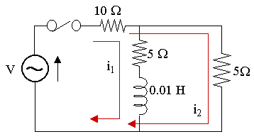
In the two-mesh network shown below, the switch is closed at t = 0 and the voltage source is given by V = 150 sin 1000t V. Find the mesh currents i1 and i2 as given in the diagram.
2 mesh circuit diagram

Example 4

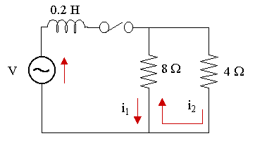
The switch is closed at t = 0 in the two-mesh network shown below. The voltage source is given by V = 30 sin 100t V. Find the mesh currents i1 and i2 as given in the diagram.
2 mesh circuit diagram

No hay comentarios:

Publicar un comentario