How to Use IR LED and Photodiode with Arduino
In this post I am going to show you how to use and program IR LED and
Photodiode pair with Arduino to detect obstacles in a short range.
Before going to do the project let us have a brief look at the IR LED
and Photodiode.
IR LED:
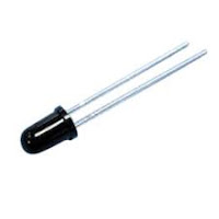
 IR LED means Infrared Light Emitting Diode. The IR LED emits Infrared light which is not
visible to human eye. we can find these IR LED's in our TV Remotes. IR
LED's works like normal LED's but the material used in the core is
different, it emits Infrared Light when current passed through it. These
IR LED are used to detect obstacles ahead of the robot. The IR LED
emits IR light which gets reflected if any obstacle is present in the
direction of emitted IR ray, the reflected IR ray caught by Photodiode
which calculates the reflected light strength. The higher the reflected
IR
IR LED means Infrared Light Emitting Diode. The IR LED emits Infrared light which is not
visible to human eye. we can find these IR LED's in our TV Remotes. IR
LED's works like normal LED's but the material used in the core is
different, it emits Infrared Light when current passed through it. These
IR LED are used to detect obstacles ahead of the robot. The IR LED
emits IR light which gets reflected if any obstacle is present in the
direction of emitted IR ray, the reflected IR ray caught by Photodiode
which calculates the reflected light strength. The higher the reflected
IRray strength, the closer is the obstacle and vice-verse
Photodiode:
 Photodiode
is a light sensitive semi-conductor diode which converts the light
energy into voltage or current based on the mode of operation. In
general Photodiodes are operated in reverse bias condition. The clear
Photodiode can detect visible and IR rays to limit the Photodiode to
detect only IR rays a black cotting is applied to the glass of the
Photodiode. The photodiode allows the current to pass through it if the
photodiode is exposed to IR rays and it doesn't allow current to pass
through it if no IR rays falls on it. The amount of current passed
through the photodiode is directly proportional to amount of IR rays
falls on it.
Photodiode
is a light sensitive semi-conductor diode which converts the light
energy into voltage or current based on the mode of operation. In
general Photodiodes are operated in reverse bias condition. The clear
Photodiode can detect visible and IR rays to limit the Photodiode to
detect only IR rays a black cotting is applied to the glass of the
Photodiode. The photodiode allows the current to pass through it if the
photodiode is exposed to IR rays and it doesn't allow current to pass
through it if no IR rays falls on it. The amount of current passed
through the photodiode is directly proportional to amount of IR rays
falls on it.IR LED and Photodiode Project:
In
this project I am going to show you How to use the IR LED and Photodiode
pair to detect the obstacle in-fornt of it. I am going to program the
Arduino such that, If an obstacle is present before the IR LED and
Photodiode pair with in the threshold range then a buzzer will ring.
Materials required:
1) Arduino 2) IR LED 3) Piezo buzzer 4) some Wires.
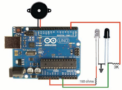
Circuit diagram:
How circuit works:
In the above circuit the Photodiode is operated in Reverse bias
condition i.e., the long leg of photodiode goes to ground and the short
leg is connected to 5 Volts supply through 3 K ohms resistor. When the
photodiode detects IR rays from the IR LED which is reflected by an
obstacle the photodiode conducts then, the current goes to the ground
through the photodiode so, the current to the analog pin A0 of Arduino
is low so that, we will get low values (around 500) from the analog pin
A0 of arduino. In case of no IR rays falls on the photodiode the
photodiode doesn't conduct so the current from the digital pin 2 goes to
analog pin A0 through the 3 K ohms resister so, the readings from the
analog pin A0 of Arduino will be around 900.
Program :
int pd=2; //Photodiode to digital pin 2int buzz=13;//piezo buzzer to digital pin 13int senRead=0;//Readings from sensor to analog pin 0int limit=850;//Threshold range of an obstaclevoid setup() { pinMode(pd,OUTPUT); pinMode(buzz,OUTPUT); digitalWrite(pd,HIGH);//supply 5 volts to photodiodedigitalWrite(buzz,LOW);//set the buzzer in off mode (initial condition)Serial.begin(9600);//setting serial monitor at a default baund rate of 9600} void loop() { int val=analogRead(senRead);//variable to store values from the photodiodeSerial.println(val);// prints the values from the sensor in serial monitorif(val <= limit)//If obstacle is nearer than the Threshold range{ digitalWrite(buzz,HIGH);// Buzzer will be in ON statedelay(20); } else if(val > limit)//If obstacle is not in Threshold range{ digitalWrite(buzz,LOW);//Buzzer will be in OFF statedelay(20); } }
How program works:
The
program starts with Initializing variables photodiode 'pd' with digital
pin 2, buzzer 'buzz' with digital pin 13, sensor readings 'senRead' to
analog pin 0 and the limit variable is set to 500 (reading from the
sensor). In the 'void setup()' method the pin mode is definde with the
function 'pinMode(variable,OUTPUT/INPUT)'. In the 'void loop()' method
the 'val' variable stores the readings from the sensor. The
'Serial.println(val);' method is used to print the values from the
sensor to the serial monitor. I had used an if - else ladder to set the
buzzer in ON state when the obstacle is in the Threshold range otherwise
the Buzzer will be in OFF state.
If you have any trouble related to this post then, express it in the comment box below.
http://henrysbench.capnfatz.com/henrys-bench/arduino-sensors-and-input/arduino-ir-obstacle-sensor-tutorial-and-manual/
Arduino IR Obstacle Sensor: Tutorial and Manual
Contents [show]
Arduino Infrared Collision Avoidance
 This
is yet another one of those modules with cool possibilities. You
could for example, sound an alarm when something got too close or you
could change the direction of a robot or vehicle.
This
is yet another one of those modules with cool possibilities. You
could for example, sound an alarm when something got too close or you
could change the direction of a robot or vehicle.The device consists of an Infrared Transmitter, an Infrared Detector, and support circuitry. It only requires three connections. When it detects an obstacle within range it will send an output low.
How to Purchase
There are several different styles of these modules available. If this particular one suits your needs, you can purchase one from the sellers below:IR Obstacle Detection Module Pin Outs
The drawing and table below identify the function of module pin outs, controls and indicators.| Pin, Control Indicator | Description |
|---|---|
| Vcc | 3.3 to 5 Vdc Supply Input |
| Gnd | Ground Input |
| Out | Output that goes low when obstacle is in range |
| Power LED | Illuminates when power is applied |
| Obstacle LED | Illuminates when obstacle is detected |
| Distance Adjust | Adjust detection distance. CCW decreases distance. CW increases distance. |
| IR Emitter | Infrared emitter LED |
| IR Receiver | Infrared receiver that receives signal transmitted by Infrared emitter. |
Arduino IR Obstacle Collision Module Tutorial
Connect the Arduino to the Detection Module
Use the picture below. It only requires three wires.
 Copy, Paste and Upload the Sample Sketch
// IR Obstacle Collision Detection Module
// Henry's Bench

int LED = 13; // Use the onboard Uno LED
int isObstaclePin = 7;  // This is our input pin
int isObstacle = HIGH;  // HIGH MEANS NO OBSTACLE

void setup() {
  pinMode(LED, OUTPUT);
  pinMode(isObstaclePin, INPUT);
  Serial.begin(9600);

}

void loop() {
  isObstacle = digitalRead(isObstaclePin);
  if (isObstacle == LOW)
  {
    Serial.println("OBSTACLE!!, OBSTACLE!!");
    digitalWrite(LED, HIGH);
  }
  else
  {
    Serial.println("clear");
    digitalWrite(LED, LOW);
  }
  delay(200);
}
Test the Tutorial Sketch
Move your hand towards the IR LEDs. As you near them, the Output LED on the module and the LED for pin 13 on your Arduino will illuminate. Open your serial monitor and vary the distance of your hand while viewing the serial monitor. The output should look like the picture below:
https://tkkrlab.nl/wiki/Arduino_KY-005_Infrared_emission_sensor_module
Arduino KY-005 Infrared emission sensor module
WARNING
this page is a copy/past of a bad google translation so it might
contain errors. If you see a error help us to make it better and log in
and change it. Big thanks!

Buy on deal extreme sensor or kit

Buy on deal extreme sensor or kit
Contents
Infrared transmitter module
This is their specific physical mapThis time we want to introduce infrared transmitter and receiver modules, in fact, they are now in our daily life. They play an important role in lots of household appliances and are used in devices such as air conditioning, TV, DVD, etc., It is based on wireless sensing, but also can be a remote control, very easy to use.
Products
- Infrared emitter converts electrical energy into near-infrared light. It is also known as infrared emitting diode. Its structure is similar with a general light emitting diode, but made of a different semiconductor material.
- The infrared receiver is set to receive, amplify, and demodulate the near-infrared light into a digital signal.
- The principle of infrared communication Let's look at the structure of the infrared receiver: there are two important elements insaide an infrared receiver, named the IC and PD. IC is the receiver processing element, mainly composed of silicon crystals and circuits, is a highly integrated device, its main function is to filter, shape, decode. Photodiode PD's main function is to receive the optical signal Number.
Raspberry Pi experiment
Notes
- Infrared emitting diodes:
infrared emission tube and then Closed head should be paired with, otherwise it will affect the sensitivity;
- Infrared receiver:
Use
We first look at the diagram, to understand the infrared transmitter and receiver module specific connection with the Arduino Note: The above circuit is based on our above that kind protel schematic structures, and meet the specific pin assignment Shown in the schematic. Well, the test circuit there, look at the code under test right now This time we use to two Arduino control board, a main transmitter (Master), one as a slave receiver (Slave), Own specific set. We can according to the above schematic wiring and fixed infrared transmitter and receiver modules, here I We can work together to test it.Hardware Requirements
- Arduino controller × 1
- USB data cable × 1
- the infrared transmitter module × 1
- the infrared receiver module × 1
Example Code
# Include <IRremote.h>
int RECV_PIN = 11; // define input pin on Arduino
IRrecv irrecv (RECV_PIN);
decode_results results;
void setup ()
{
Serial.begin (9600);
irrecv.enableIRIn (); // Start the receiver
}
void loop () {
if (irrecv.decode (& results)) {
Serial.println (results.value, HEX);
irrecv.resume (); // Receive the next value
}
}
Main emission part of the code:
# Include <IRremote.h>
IRsend irsend;
void setup ()
{
Serial.begin (9600);
}
void loop () {
for (int i = 0; i <50; i + +) {
irsend.sendSony (0xa90, 12); // Sony TV power code
delay (40);
}
}


No hay comentarios:
Publicar un comentario