LED Charlieplexing - The theory
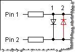
Ok, the principle behind Charlieplexing is fairly simple. If you hook up 2 LED's between 2 micro-controller pins with 1 anode towards pin 1 and one anode towards pin 2, you turn on LED1 by setting pin 1 HIGH and pin 2 LOW. To turn LED2 on you reverse it - Set pin 1 LOW and pin 2 HIGH. See the first image below.
This of course means that only one of the LED's can be on at any time. Microcontrollers operate so quickly that you can just alternate their on states very quickly and it will look like both are on all the time.
Now at this point, you'll probably be saying "Well, so what? I could turn 2 LED's on using 2 pins without all this extra complexity..."
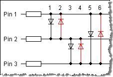
If you add a third micro-controller pin to the equation it starts getting interesting. Now you can turn on 6 LED's. Basically, you have the same setup as with 2 pins, but you also have the same setup between pin 2 and 3 and between pin 1 and 3. See the second image below.
To turn on the LED's connected to pin 1 and 3, you need to disconnect pin 2 from the circuit, and then just set pin 1 and 3 HIGH and LOW based on which LED you want to turn on. Luckily, the Arduino allows you to do this. If you change a pin to an input, it basically turns into a big resistance, which is close enough to being disconnected for this to work.
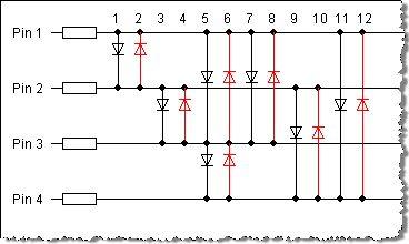
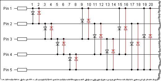
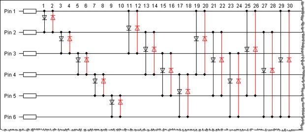
Now if you look at the third image, you can see what this looks like for 4 pins (12 LED's) and the fourth image shows you what it looks like for 5 pins (20 LED's).
You'll notice that it becomes rather interesting to wire it up by the time you get to 30 LED's with 6 pins. This for me seems like the limiting factor when building this.
This of course means that only one of the LED's can be on at any time. Microcontrollers operate so quickly that you can just alternate their on states very quickly and it will look like both are on all the time.
Now at this point, you'll probably be saying "Well, so what? I could turn 2 LED's on using 2 pins without all this extra complexity..."
If you add a third micro-controller pin to the equation it starts getting interesting. Now you can turn on 6 LED's. Basically, you have the same setup as with 2 pins, but you also have the same setup between pin 2 and 3 and between pin 1 and 3. See the second image below.
To turn on the LED's connected to pin 1 and 3, you need to disconnect pin 2 from the circuit, and then just set pin 1 and 3 HIGH and LOW based on which LED you want to turn on. Luckily, the Arduino allows you to do this. If you change a pin to an input, it basically turns into a big resistance, which is close enough to being disconnected for this to work.
Now if you look at the third image, you can see what this looks like for 4 pins (12 LED's) and the fourth image shows you what it looks like for 5 pins (20 LED's).
You'll notice that it becomes rather interesting to wire it up by the time you get to 30 LED's with 6 pins. This for me seems like the limiting factor when building this.
No hay comentarios:
Publicar un comentario